clock icon
This lesson should take approximately 30-40 minutes to complete.

This unit provides an overview of the general design practices and briefly discusses specific design practices that are unique to each retrofitting measure.

  • Describe the components of a field investigation
  • Explain the process for analyzing an existing structure for retrofitting
  • Identify the five retrofitting measures for flood-prone residential structures
Lesson List: Introduction to Retrofitting; Regulatory Requirements; Parameters of Retrofitting; Determination of Hazards; Design Practices (Starting)
Design Practices
  • This unit focuses on applying the anticipated loads discussed in Unit 4 to the existing site/structure and designing an appropriate retrofit measure
  • The unit includes:
    • General design practices common to all projects
    • Elevation
    • Relocation
    • Dry floodproofing
    • Wet floodproofing
    • Floodwalls and levees
    The Design Process

    The design process is straightforward, but technically intensive. It will result in:

    • Generation of construction plans to submit for building permitting
    • Mitigation of potential damages from flood and other natural hazards
    sample of the Design Process
    Field Investigation (1 of 3)

    Detailed information is required to make decisions about, and calculations for, retrofit measures, including:

    1. Local building requirements
    2. Surveys (structure, topographic, site utilities)
    3. Hazard determinations
    4. Documentation of existing mechanical, electrical, and plumbing systems
    5. Homeowner preferences
    6. Homeowner coordination
    7. Maintenance programs and emergency action plans
    Field Investigation (2 of 3)
    1. Designers should review the selected retrofitting measure concept with the local building official to identify local design standards or practices that should (or must) be integrated.
    2. A detailed survey of the site will supplement the information gathered during the low point of entry determination.* This includes structure survey, topographic survey, and site utilities survey.
    3. The risk determinations (Unit 3) and hazard determinations (Unit 4) should be reviewed to confirm the flood protection design level and required height of retrofitting method.
    4. For elevation, relocation, and dry/wet floodproofing measures, documentation of the condition of the existing structure and building systems is important.
      • Mechanical, Electrical, Plumbing, and Related Building Systems Data Sheet can be used to document the condition of the existing systems
    5. Designers should confirm the homeowner’s preferences as outlined in Unit 3.
    6. The process of homeowner coordination involves reviewing design options, costs, specific local requirements, and other applicable design components with the homeowner.
    7. Retrofitting measures will remain useful throughout the life of the measure with the implementation of appropriate maintenance programs.

    The next screen explains the three types of surveys

    * Low point of entry determination identifies the lowest floor and each of the structure’s openings

    Field Investigation (3 of 3)
    Structure Survey: Vertical elevation assessment throughout the structure at openings where floodwater may enter.

    Topographic Survey: A site plan or map of the area developed by a State-registered Professional Land Surveyor. The plan should include the low point of entry determination information, as well as general topographic and physical features.

    Site Utilities Survey: Identification of above- and below-ground site utilities.
    Analysis of Existing Structure

    The structure’s ability to withstand the additional loads created as a result of retrofitting is an important design consideration.

    The steps involved in the analysis include:

    1. Structural reconnaissance
    2. Determine the capacity of the existing footing and foundation system; analyze the loads that would be imposed by the retrofitting measure
    3. Calculate the capacity of the existing structure to resist the additional loads imposed by the retrofitting measure
    Structural Reconnaissance

    Gather information from the following sources to complete structural reconnaissance:

    • Construction drawings
    • Building permits office
    • Renovation records
    • Contractors who have recently performed work
    • Home inspection report, if home is newly purchased
    Sample of a Structural Reconnaissance Worksheet
    Figure 5-3 structural reconnaissance worksheet
    Footings and Foundation Systems
  • The foundation system of a house:
    • Supports the house by transmitting loads to the ground
    • Serves as an anchor against uplift and other loads
  • Retrofitting measures change the dynamics of the forces acting on a house
  • graphic showing Foundation Systems loading and footing reactions
    Loads Imposed by Retrofitting Measure
    • If the stress caused by the expected loads is greater than the code-allowable stresses for the expected failure mode, reinforcing is required
    • Loads to consider include but are not limited to building dead, live, snow, flood, wind, and seismic loads (if applicable)
      • For dead loads, the worksheet in Figure 5-5 can be used to estimate the weight of a structure
      • Live loads are produced by the occupancy of the building, not including environmental loads
      • Roof snow loads vary according to the geography, roof slope, thermal exposure, and importance factors

    Calculations for dead, live and snow loads are explained in Sections 5.2.10 – 5.2.14 of FEMA P-259. Flood, wind and seismic loads are explained in Chapters 3 and 4 of FEMA P-259.

    Retrofitting Methods
    Retrofitting Methods-Elevation, relocation, dry floodproofing, wet floodproofing, floodwalls/levees
    Elevation
    Raising a structure to place the lowest floor at or above the designated design flood elevation (DFE) on an extended support structure or fill
    house on elevated foundation
    Elevation

    Residential structures that can be elevated:

    Houses over a crawlspace

    • Elevated on either solid or open foundation walls

    Houses over basements

    • Elevated on either solid or open foundation walls

    Houses on piles, piers, or columns

    • Temporary relocation of the home may be necessary

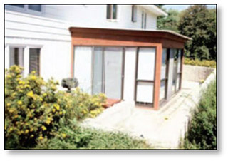
    Slab-on-grade houses

    • Wood frame vs. masonry—different elevation methods
    Houses Over a Crawlspace
  • Generally the easiest and least expensive houses to elevate
  • Usually one- or two-story houses built on a masonry crawlspace wall, allowing for access in placing steel beams underneath the house for lifting
  • In most cases, the low clearance in crawl spaces prevents utilities from being placed under the home, limiting the need to relocate utilities during elevation
  • Can be elevated on:
    • Extended solid foundation walls
    • Open foundation such as masonry piers
    Houses Over Basements
  • More difficult to elevate than houses over crawlspaces, as mechanical and heating, ventilation, and air conditioning (HVAC) equipment are often located in the basement
  • Basement walls may have already been extended to the point where they cannot structurally withstand flood forces
  • Can be elevated on:
    • Solid foundation walls by creating a new masonry-enclosed area on top of an abandoned and filled-in basement
    • Open foundation, such as masonry piers, by filling in the old basement
    Elevation on Solid Perimeter Foundation Walls
    • A cross section of an elevated wood-frame house with extended masonry-enclosed area on top of an abandoned and filled-in basement
    • Similar to the cross section of house elevated on extended solid foundation walls over a crawlspace
    cross section of an Elevation on Solid Perimeter Foundation Walls
    Elevation on Piers
  • Cross section of an elevated wood-frame house on a new or extended pier foundation
  • Similar to the cross section of a house on new reinforced piers on top of existing filled-in basement
  • Cross section of Elevation house on piers-Note: Flood-resistant materials and methods required below DFE
    Elevation of Slab-on-Grade Houses
  • Most difficult type of house to elevate
  • Can raise the structure with or without the slab and use a first floor that is typically composed of wood or masonry
  • There are different elevation methods for wood-frame and masonry slab-on-grade houses
  • Slab-on-Grade Houses: Wood Frame

    The following alternatives apply for this elevation method:

    • Elevating without the slab and using a new first floor constructed of wood trusses
    • Elevating with the slab intact
    sample cross section of a slab on grade house-wood frame-Note: Flood resistant materials and methods required below DFE
    Slab-on-Grade Houses: Masonry

    The following alternatives apply to this elevation method:

    • Elevate with slab intact
    • Elevate without the slab, using first floor constructed of wood framing
    • Install elevated concrete slab within structure
    • Install elevated wood-frame floor system within structure
    • Create new masonry livable area on top of existing home
    • Create new wood-frame livable area on top of existing home
    Field Investigation Concerns

    Field investigations for elevating a building should include:

    • Property inspection and existing data review
    • Code search

    Designers can use the Elevation Field Investigation Worksheet to record information

    Sample Elevation Field Investigation Worksheet
    Design

    The design process for an elevated structure is presented here

    Detailed descriptions of each step can be found in Section 5E.3 of FEMA 259

    Design Process- Step 1-Calculate the vertical loads, Step 2-Calculate the lateral loads, Step 3-check ability of existing structure to withstand additional loading, Step 4-Analyze the existing foundation , Step 5-design  the new foundation walls, Step 6-design top of foundation wall connections, step 7-design sill plate connections, step 8-design new access, step-9-design utilities extensions, step 10-specify the increased insulation requirements
    Construction Considerations

    Prior to elevating any house:

    • Obtain all required permits and approvals
    • Ensure all utility hook-ups are disconnected (plumbing, phone, electrical, cable, mechanical)
    • Estimate the lifting load of the house
    • Identify the best location for the principal lift beams, lateral support beams, and framing lumber, and evaluate their adequacy

    Additional construction considerations, organized by structure and elevation type, are located in Section 5E.4

    Relative Costs for Elevation
    Link to a larger version of Table 3-1: Relative Costs for Elevation Pdf
    Table 3-1 Relative costs of elevating a home with headings stating construction type, existing foundation, retrofit, relative cost
    Relocation
    Moving a structure to a location that is less prone to flooding and flood-related hazards such as erosion
    House on  trailer/wheels for relocation
    Relocation Process
    • Relocation is the retrofitting measure that can offer the most protection from future flooding
    • The new site is often selected by the homeowner in consultation with the designer or community officials


    Relocation Process-Step 1-select the house moving contractor, step 2-analyze the existing site and structure, step 3-select, analyze, and design the new site, step 4-Prepare the existing site, step 5-analyze and prepare the moving route, step 6-prepare the structure, step 7-prepare the new site, step 8-move the structure, step9-restore the old site.
    Select the House Moving Contractor

    Critical step in relocation

    • The designer can help the homeowner select a home moving contractor
    • The Relocation Contractor Selection Checklist can be used to record the key elements of selection


    Sample of a Relocation Contractor Selection Checklist
    Analyze the Existing Site and Structure

    When analyzing the existing site and structure, consider:

    • Is there enough space around the structure to accommodate lifting beams and truck wheels?
    • Can the structure be lifted as one piece?
    • How much bracing will be required to successfully move the structure?
    • Will the structure survive the lift and move proposed?
    • Which utilities must be disconnected and where?
    • What local regulations govern demolition of the remaining portions of the structure (foundation and paved areas)?
    • To what standard must the site be restored?
    Select New Site and Prepare Existing Site

    Examine potential sites for:

    • Floodplain location
    • Utility extension feasibility
    • Accessibility for both the house movers and the new site construction crews
    • Permitting feasibility of the existing house on the new lot

    Preparation of the existing site includes clearing all vegetation from the area in and around the footprint of the house to clear a path to allow the insertion of beams for lifting supports.

    Analyze and Prepare the Moving Route
    Identify route hazards, including narrow passages, bridge height and weight limits, utility conflicts, fire hydrants, road signs, steep grades, traffic signals, and tight turns around buildings, bridges, and overpasses
  • Obtain approvals for the area from which the structure is being moved and also from jurisdictions through which the structure will pass and its ultimate destination
  • The moving contractor should be responsible for route preparation, including the raising or relocation of utilities by utility companies, road/highway modifications, traffic lights, signage, etc.
  • Clear/grub overland areas, where necessary
  • Preparing the Structure and New Site

    The steps for preparing the structure include:

    • Disconnect utilities
    • Cut holes in foundation wall for beams
    • Install beams
    • Install jacks
    • Install bracing
    • Separate structure from foundation
    house on pallets and frame ready to be moved
    Preparing the New Site

    The steps for preparing the new site include:

    • Design foundation
    • Design utilities
    • Excavate and prepare new foundation
    • Construct support cribbing
    • Construct foundation walls
    picture of a cement block foundation with a house ready to relocated.
    Move Structure and Restore Old Site
    Movement of the existing structure includes the excavation / grading of a temporary roadway, attachment of the structure to a trailer, transport, attachment of the structure to the new foundation, and landscaping.

    Restoration of the old site should be conducted in accordance with local regulations. More details on restoring the old site can be found in Section 5R.9 of the manual.
    Relative Costs for Relocation
    Relative costs for relocation table
    Dry Floodproofing
    A flood retrofitting technique in which the portion of a structure below the flood protection level (walls and other exterior components) is sealed to be watertight and substantially impermeable* to floodwaters
    Dry Floodproofing graphic-Maximum protection level is 3 feet (including freeboard), backflow valve prevents sewer and drain backup, external coating or covering impervious to floodwater, shields for opening.
    Dry Floodproofing Selection

    Dry floodproofing mitigation measures:

    • Watertight shields for doors and windows
    • Reinforced walls
    • Membranes and sealants
    • Drainage collection systems and sump pumps
    • Check valves
    • Anchoring
    Dry flooding Selection-Field investigation, selection and design, confirm ability of structure to accommodate dry floodproofing measure(s), select and design sealants and shields, select and design drainage collection systems, select and design sump pumps, select and design backflow valves, provide for emergency power for drainage system operation, prepare emergency operations plan, prepare operations and maintenance plan, construction of dry floodproofing measures.
    Dry Floodproofing Applications

    Buildings that are dry floodproofed may be subject to enormous hydrostatic pressure and imbalanced forces against the foundation and exterior walls and floor surfaces. It should only be used under the following conditions:

    • Short duration flooding
    • Low velocity flooding
    • Depth less than 3 feet

    Dry floodproofing is NFIP- compliant for non-residential structures only

    sample of Dry Floodproofing Applications
    Evaluation of Existing Structure
    • Important step in the development of type, size, and location of the sealant and shield systems
    • Design process used to determine the ability of the existing structure and foundation to resist the expected flood- and non-flood-related forces

    Figure 5D-10 presents a flow chart representation of the design process for a sealant or shield system

    Selection and Design of Sealant Systems
  • Selection depends on the ability of the manufacturer’s product to withstand the depth and duration of flooding expected and the type of construction materials required
  • Processes for selecting the following systems are presented in the manual:
    • Coatings
    • Wrapped Systems
    • Brick Veneer Systems
    Cross section of Design of Sealant Systems
    Selection and Design of Shield System

    Selection is based on the ability of the selected material to:

    • Structurally secure the opening
    • Be compatible with existing construction materials
    • Be effective for the duration and depth of flooding expected

    The processes for selecting plate shields is presented in Section 5D.7.1 of the manual

    Drainage Collection Systems

    Underdrain systems may reduce flood loads for short duration flooding by moving floodwater away from the building’s foundation. Varieties include:

    • French drains, exterior underdrain systems, or interior drain systems

    Sump Pumps prevent accumulations of water within the residence, often around important utilities.

    • They can be submersible or pedestal
    • If relying on for dry floodproofing, verify the pumps are functioning
    • Detailed field investigation is needed to determine if a sump pump is feasible
    • Sump pumps should be coordinated with other floodproofing methods
    Backflow Valves and Emergency Power
    Backflow Valves and Emergency Power

    Backflow valves can help prevent backflow through the sanitary sewer and/or drainage systems into the house.

    • Detailed information must be obtained about the existing structure to determine if backflow valves are feasible
    • Design process is outlined in Section 5D.10.2

    Emergency power (generators) can be installed in homes if the proper guidelines are observed.

    • Small, portable residential generators can be used
    • Unit capacity should match the anticipated maximum load
    • Essential equipment/appliances are outlined in Table 5D-1
    Non-Residential Construction

    Dry floodproofing options for non-residential construction include:

    • Permanent closure of non-essential vulnerable openings
    • Watertight core areas
    • Enhanced flood shields
    • Pressure relief systems to protect against structural failure
    Wet Floodproofing
    Modifying a structure to allow floodwaters to enter in a way that damage to the structure and its contents is minimized
    graphic of Wet Floodproofing shows how a structure is modified to limit the damage of floodwaters.
    Figure 1-10. Wet floodproofed structure
    Wet Floodproofing (Continued)

    This section introduces the following concepts related to wet floodproofing:

    • Protection of the structure
    • Design of openings is for intentional flooding of enclosed areas below the DFE
    • Use of flood-resistant materials below the DFE
    • Adjustment of building operations and maintenance procedures
    • Emergency preparedness for actions that require human intervention
    • Design of protection for the structure and its contents, including utility systems and appliances
    collage of different types of wet floodproofing-fence around ac units, vents in basement to let water pass though.
    Protection of the Structure

    Failure of structural components when subjected to inundation is a major cause of structural damage. Those components, typical failure modes, and related design considerations are briefly explained below.

    • Floodwater can affect a structure’s foundation by eroding supporting soil, scouring foundation material, and undermining footings. Footing depth, anchoring of the structure to the foundation, and lateral support in foundation walls should be considered in design.
    • Wet floodproofing will not be successful if the cavity space does not fill with water and drain at a rate equal to the floodwater rate of rise and fall. Insulation within cavity walls subject to inundation should be designed of flood-damage-resistant material.
    • Solid walls may absorb moisture and associated contaminants and should have both exterior and interior protective cladding to guard against absorption.
    Use of Flood-Resistant Materials Cross Reference Icon
  • All materials exposed to floodwater must be durable, resistant to flood forces, and retardant to deterioration caused by repeated exposure to floodwater
  • Interior materials such as wall finishes, floors, ceilings, roofs, and building envelope openings can suffer damage from inundation, which can lead to failure or an contamination and mold issues
  • List of appropriate materials can be found in NFIP TB 2-08, Flood Damage-Resistant Materials Requirements
  • Cover of Technical Bulletin 2-Flood Damage-Resistant Materials Requirements
    Operations, Procedures, Preparedness

    Consider the following when wet floodproofing:

    • Flood Warning System. Wet floodproofing, in most cases, requires some human intervention. It is extremely important to have adequate time to execute actions. May be accomplished by monitoring local weather reports, the NWS alert system, or a local warning system.
    • Inspection and Maintenance Plan. Wet floodproofing design requires periodic inspection and maintenance to ensure components can operate under flood conditions.
    • Emergency Operations Plan. Includes adjustments to or relocation of structure contents and utilities. A list of specific actions and the location of materials needed to perform these actions should be developed and provided to those responsible for executing the plan.
    Protection of Utility Systems-Electrical

    Electrical systems:

    • Raise/relocate equipment and devices above the DFE
    • Seal outside wall penetrations; mechanically protect wiring system in flood-prone locations
    • Seal out moisture
    • Add Ground Fault Circuit Interrupting (GFCI) breakers
    Elevated AC system
    Figure 5W-1. Elevated air conditioning system
    Protection of Utility Systems-HVAC Systems

    HVAC systems:

    • Maintain equipment clearances and access by code and/or manufacturer
    • Provide adequate combustion air for fuel-burning equipment
    • Modify and/or maintain proper venting for fuel-burning equipment
    • Eliminate ductwork below the DFE
    Elevated AC system
    Figure 5W-1. Elevated air conditioning system
    Protection of Utility Systems-Fuel Supply/Water System

    Fuel Supply/Storage Systems:

    • Use flexible connections
    • Support and anchor tanks to resist flood forces (assume tank is empty in design)
    • Move fuel tank with relocated equipment
    • Use automatic cut-off valves

    Water System:

    • Minimize plumbing fixtures below the DFE
    • Modify fixtures to prevent backflow
    • Protect system components from high-velocity flow
    • Modify the well top using watertight casing
    graphic of a propane tank with galvanize 48-inch long, 3/4 inch diameter, double-headed ground anchor with 6-inch single helix auger.
    Figure 5W-6. Fuel tank anchored from two sides
    Protection of Utility Systems-Sewer System

    Sewer Systems:

    • Install and/or maintain a check valve or sewer backflow prevention valve
    • Install an effluent ejector pump
    • Provide a backup electrical source
    • Seal septic tanks to prevent contamination
    • Adequately anchor septic tank to withstand buoyancy forces
    graphic of Sewer System with a typical installation of an exterior backflow valve.
    Figure 5W-7. Backflow valve – a check valve and gate valve with an effluent pump bypass
    Floodwalls and Levees Terminology Icon
    Floodwall: A flood retrofitting technique consisting of barriers designed to keep floodwaters from coming into contact with the structure.

    Levee: A manmade structure built parallel to a waterway to contain, control, or divert the flow of water. A levee system may include concrete or steel floodwalls, fixed or operable floodgates and other closure structures, pump stations for rainwater drainage, and other elements, all of which must perform as designed to prevent failure.
    Floodwalls and Levees (Continued)

    The design and construction process for both floodwalls and levees includes:

    • Field investigation
    • Design
    • Seepage concerns
    • Leakage concerns (floodwalls only)
    • Construction
    • Drainage
    Residential floodwall
    Residential Levee
    Field Investigation Considerations

    Floodwalls:

    • Using previous floods to define affected areas
    • Evidence of seepage in foundation walls
    • Plan of action for relief of hydrostatic pressure on foundation/exterior walls
    • Floodwall options
    • Adjustment of utilities
    • Construction activities and level of disruption
    Floodwall Design

    Types of floodwalls:

    • Gravity
    • Cantilever
    • Buttressed
    • Counterfort
    graphic of different Floodwall Design-gravity wall, cantilever wall, buttress, counterfort
    Types of Floodwalls Terminology Icon
    Gravity: Uses its weight for stability. Structural stability is attained by effective positioning of the mass of the wall.

    Cantilever: A reinforced-concrete wall (cast-in-place or built with concrete block) that relies on a vertical support and horizontal footing to retain the mass behind the wall.

    Counterfort: Similar to a cantilever retaining wall except that it can be used where the cantilever is long or when very high pressures are exerted behind the wall.

    Buttressed: Similar to a counterfort wall except that the transverse support walls are located on the side of the stem, opposite the retained materials.
    Floodwall Design
    Design of floodwalls can be summarized in an 8-step process:
    1. Determine wall height and footing depth
    2. Assume dimensions
    3. Calculate forces
    4. Calculate factor of safety against sliding
    5. Calculate factor of safety against overturning
    6. Calculate eccentricity
    7. Calculate soil pressures
    8. Select reinforcing steel

    The process can be simplified by assuming certain design parameters.

    Floodwall Seepage and Leakage Considerations
    Seepage through the floodwall
    • Expansion and construction joints must be constructed with appropriate waterstops/sealants

    Seepage under the floodwall

    • Structure design may include impervious barriers or cutoffs under floodwalls

    Leakage between the floodwall and residence

    • The gap between floodwall and residence should be filled with a waterproof material
    Construction Considerations
    Inspect/observe the following:
    • Adequate slope drainage
    • Proper floodwall foundation construction
    • Sealants applied per manufacturer’s requirements
    • Sump pump
    • Sample brick/decorative block
    • Maintenance requirement checklist
    Field Investigation Considerations
    Levees:
    • Whether natural topography lends itself to levee construction
    • Availability of fill material
    • Federal, State, and local regulations/ordinances
    • Coordination with Federal, State, and local officials
    • Effect of levee on natural flow of floodwaters
    • Flood velocities along the water side of the levee embankment
    Levee Design

    Standard levee design criteria were established in FEMA 259 to provide a conservative design while eliminating several steps in the USACE design process, thereby minimizing design cost:

    • Minimum settled levee height of 6 feet
    • Minimum levee crest width of 5 feet
    • Levee floodwater side slope of 1: 2.5
    • Levee land side slope (varies)
    • One foot of levee freeboard
    cross section of a typical residential Levee Design
    Relative Costs for Wet Floodproofing
    Relative Costs for Wet Floodproofing
    Levee Seepage Considerations
    Levee foundation seepage
    • Install and backfill the inspection trench with impervious material

    Levee embankment seepage

    • Mandatory inclusion of a drainage toe

    Scouring and levee slope protection

    • Stabilize embankments with vegetation or sod

    Interior levee drainage

    • Install drain pipes through levee having backflow prevention (flap gate) as well as sump pump
    Construction Considerations
    Levees:
    • Remove all ground vegetation and topsoil over full levee footprint
    • Ensure suitability of levee soil
    • Levee should be constructed in layers with proper compaction
    • Construct levee at least 5% higher than the height desired to allow for soil settlement
    • Avoid using a borrow area within 40 feet of landward toe
    • Ensure access across levee